
SMT Assembly Services
Surface-mount is where fine pitch is won or lost. Paste volume, placement force and the reflow curve decide whether a 0.4 mm BGA wets properly — long before anyone looks at the joint.
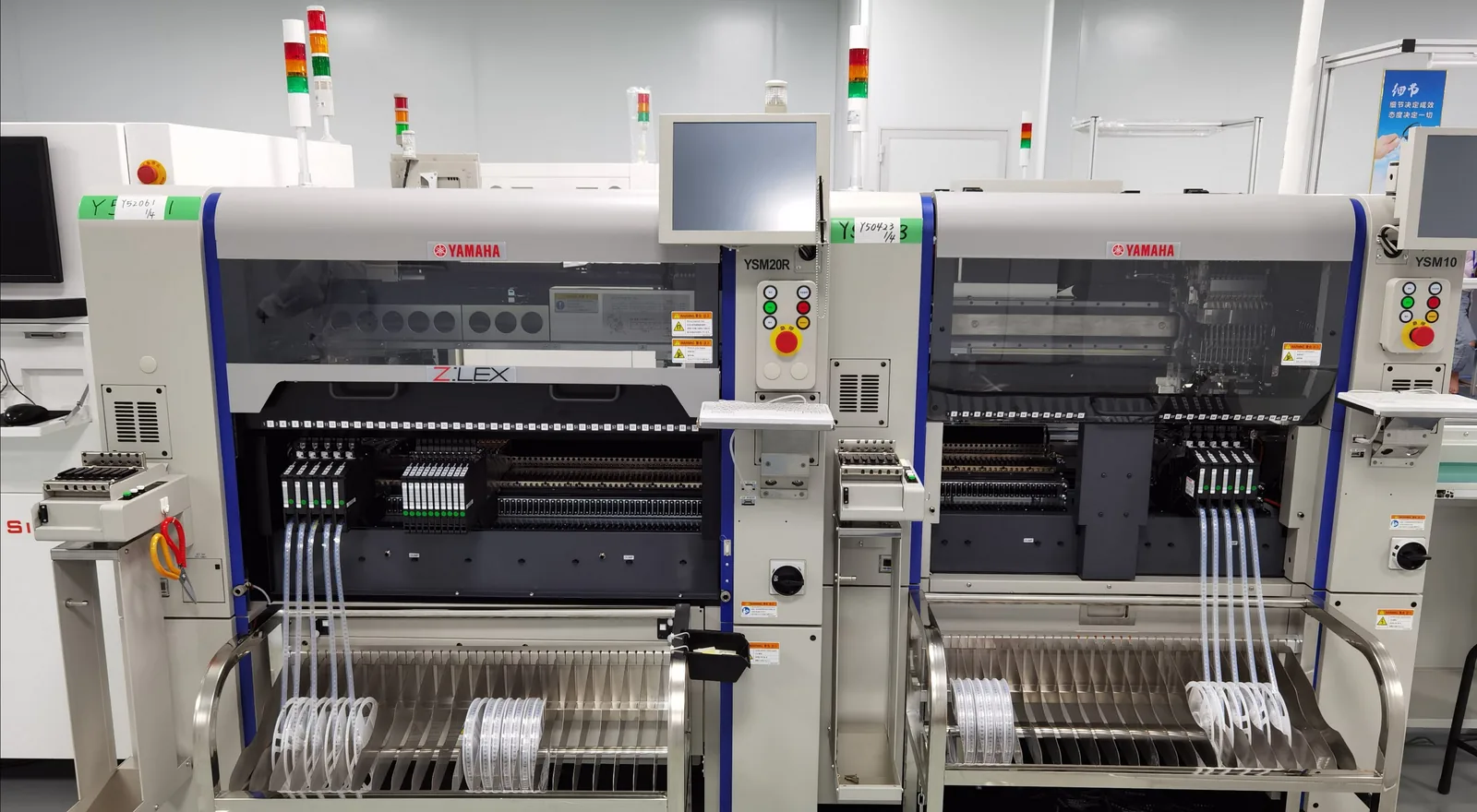
The paste print decides the joint, not the oven.
A surface-mount joint is a volume problem before it is a temperature problem. Too little paste and the fillet never forms; too much and the part floats or bridges on reflow. Both failures are already sealed in by the time the board reaches the oven, which is why the print is measured rather than trusted.
Fine pitch adds a second constraint: the stencil aperture has to release paste cleanly at an area ratio that a 0.4 mm pitch pad can still tolerate. Aperture design, stencil thickness and placement pressure are set per package at DFM review, and the first article is inspected before the run is released.
What the placement lines hold, and to what tolerance.
Placement
| Parameter | Capability |
|---|---|
| Smallest component | 01005 (0.4 × 0.2 mm); 0201 and 0402 run as standard |
| Minimum BGA pitch | 0.4 mm standard, 0.35 mm on DFM review |
| Maximum board | 560 × 480 mm |
| Throughput | 100,000 CPH on the high-speed lines |
| Stencil | Laser-cut, 0.12–0.15 mm; stepped for fine pitch |
Process and inspection
| Parameter | Capability |
|---|---|
| Paste inspection | SPI after every print, in line |
| Reflow | Convection, nitrogen available; SAC305 or SnPb |
| Joint inspection | AOI on every joint, X-ray on area-array packages |
| Standards | IPC-A-610 Class 2 standard, Class 3 on request; J-STD-001 |
| Handling | Class 0 / 1 / 2 ESD-protected lines |
Single-sided and double-sided surface-mount both run here. On a double-sided build the second pass is a thermal decision as much as a placement one, and it is quoted as part of the same order rather than as a separate job. Every build runs to IPC Class 2 standard, Class 3 on request.
Four places this process fails, and what is done about each.
Paste volume is measured after every print
A printer with closed-loop pressure feedback holds the deposit, and SPI checks it print by print. Under- or over-deposit triggers a stencil wipe and a reprint before a single component is placed. The alternative — inspecting the joints afterwards — finds the same defect one oven later, with the part already committed.
Fine pitch is a stencil problem first
At 0.4 mm pitch the aperture area ratio is the limit, not the placement machine. Apertures are designed against the pad, the stencil is thinned or stepped locally, and the print is proven on the panel before the run. A machine that can place the part cannot rescue a print that will not release.
The profile belongs to the package
Reflow is profiled per paste and per package, with thermocouples on the actual board rather than a recipe borrowed from a similar design. Nitrogen is available where an oxidation-sensitive finish or a low-activity flux needs it. The curve is recorded and reused for repeat orders instead of being re-guessed.
Area-array joints go through X-ray
BGA, LGA and QFN joints sit under the package where no camera reaches. X-ray is standard on those orders, and a first-article X-ray is part of setting up a new package — voids, bridges and missing balls are caught while the tooling can still be changed.
Fine pitch and no answer on the stencil?
Send the Gerbers, the BOM and the CPL. Aperture and profile decisions come back with the quote, not after the order.
Questions that come up on fine-pitch work.
Can you place 01005 passives on a normal production run?
01005 is the floor of what the lines place, and it needs the right nozzle, a thinner stencil and a tighter print window than 0201. It is quoted as a fine-pitch job rather than as a standard run, because the setup time is where the cost sits. 0201 and 0402 carry no such premium.
What stencil thickness will my board need?
0.12 to 0.15 mm covers most surface-mount work. Below about 0.5 mm pitch the area ratio starts to work against paste release, so the stencil is thinned or stepped locally rather than globally — a full thin stencil would starve the coarse parts on the same side.
Do you assemble both sides?
Yes. The side that tolerates the higher reflow profile goes through first, and heavy parts on the second side are reviewed for whether they survive another cycle. Bottom-side through-hole connectors are inserted after both reflows, which is what keeps the surface-mount joints from being cycled a third time.
Is nitrogen reflow necessary?
Not by default. It helps where the finish oxidises easily, where the flux activity is low, or where wetting on a small pad is marginal. It is a per-order decision made at DFM review and named in the process sheet, not a line-wide setting.
What makes a 0.4 mm BGA fail?
Three things, in order of frequency: paste volume outside the window, warpage across the package during reflow, and a profile that lets the balls collapse unevenly. All three are visible before the board is powered — which is why the print is inspected and the joints are X-rayed rather than judged by whether the board works.
Want the print and profile settled before tooling?
Send the Gerbers and the assembly drawing. Quote in 24 hours, with aperture and stencil notes attached.