Rogers + FR-4 Hybrid Stack-Ups: When the Mix Pays Off
Two resin systems through one press cycle, a 190 °C compromise profile, and why desmear behaves differently on each plastic.
Read article

Rogers laminates for RF and microwave hardware — 4003C, 4350B and RT/duroid 5880 in hybrid stack-ups, impedance modeled rather than estimated, and performance verified to 28 GHz on coupon.
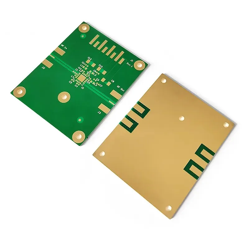
Rogers is a family of high-frequency laminates rather than one material, and two branches matter in production. PTFE-based boards such as RT/duroid 5880 hold a Dk near 2.2 with very low loss, which is why they appear in millimetre-wave designs. Hydrocarbon-ceramic boards such as RO4003C and RO4350B sit at Dk 3.55 and 3.66 and process much like FR-4, which is why most RF front-ends are built on them. Choosing between the two is an electrical and mechanical trade, not a brand preference.
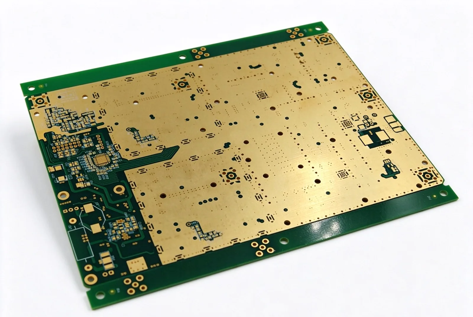
Plenty of factories quote a Rogers board by reading a grade off a datasheet and laminating it — that is the easy half. The hard half is hybrid construction: a Rogers core carrying the RF traces, FR-4 carrying digital and power, pressed into one board whose two materials expand at different rates. Get the press profile wrong and the panel looks fine leaving the press, then warps or loses registration after the first reflow. We build these as engineering projects, not as one more laminate on a list.
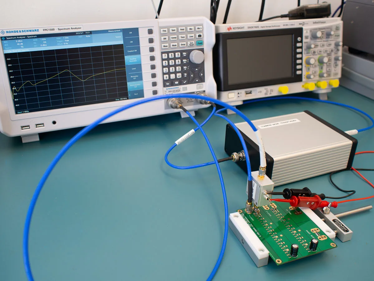
At HSX CIRCUIT that means the RF layer is modeled against the actual laminate lot before drilling, the hybrid interface is planned around CTE rather than habit, and a coupon on the panel border confirms both impedance and insertion loss — measured through 28 GHz on the benches where the design requires it. 80 CAM engineers review 6,000+ designs a month, and a Rogers enquiry gets an engineering response within 24 hours, including a stack proposal when the grade is still open.
PTFE cuts soft and smears where FR-4 would drill clean. Drill parameters are set per laminate and desmear is tuned so the via wall is prepared without attacking the low-loss dielectric — a rough via wall is a loss term that cannot be fixed downstream.
Two materials with different coefficients of thermal expansion need a press profile built for both. Staged temperature and pressure holds with matched prepreg keep the panel flat and the layer registration intact through assembly reflow, not only at press exit.
Above 10 GHz, a few microns of dielectric thickness moves Dk enough to push a line out of a ±5% window. Each RF layer is modeled against its real laminate lot, and a coupon on the panel border is measured so the number is confirmed rather than assumed.
Finish sits inside the RF path. ENIG at Au 3–6 µin is the default, immersion silver is chosen where the lowest insertion loss matters, and OSP is limited to builds with a short assembly window. Mask and plating steps are sequenced to keep thermal cycles off the low-loss material.
| Parameter | Capability |
|---|---|
| Laminate portfolio | RO4003C (Dk 3.55 / Df 0.0027) · RO4350B (Dk 3.66 / Df 0.0037) · RT/duroid 5880 (Dk 2.20 / Df 0.0009), at 10 GHz |
| RF verification | Impedance and insertion loss verified to 28 GHz on coupon, per design requirement |
| Layer count | 2–32 layers; Rogers + FR-4 hybrid stacks in one build; 50+ on inquiry |
| Impedance tolerance | ±5% standard, ±3% on request |
| Min trace / space | 0.075 mm / 0.075 mm, design-rule dependent on laminate |
| Board thickness | 0.4–6.0 mm |
| Surface finish | ENIG (Au 3–6 µin), immersion silver for low loss, OSP on request; hard gold on connector edges |
| Electrical test | 100% — flying probe or fixture, plus RF coupon measurement per lot |
UL 94 V-0 · Built to IPC-6012 / IPC-A-600 · IPC Class 2 standard, Class 3 on request · Full matrix: see Capabilities.
Send the stack-up and the frequency — a CAM engineer will model it, not guess.
28 GHz front-ends where Dk stability decides beam-steering accuracy.
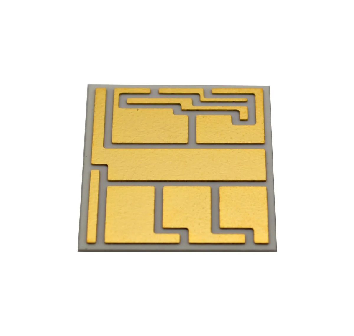
Ceramic and hybrid boards for high-power RF stages with tight thermal paths.
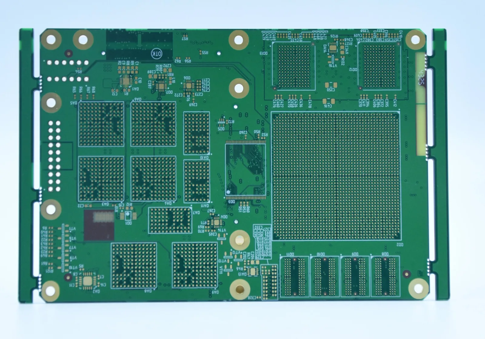
Automotive radar where loss per inch has to be counted, not estimated.
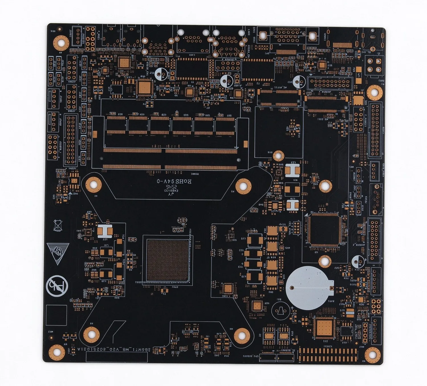
Multi-layer patch arrays with via fences and controlled feed impedance.
Two resin systems through one press cycle, a 190 °C compromise profile, and why desmear behaves differently on each plastic.
Read article
Four tolerances, four sensitivities, and why the root-sum-square lands at 7.1% while the worst case reaches 12%.
Read article
Alumina at 20–24 W/m·K and AlN at 170 against 0.2–0.3 for FR-4, plus the crossover arithmetic that decides which one ships.
Read article
Both are hydrocarbon-ceramic laminates that process much like FR-4. 4003C is the cheaper starting point for most RF front-ends; 4350B has the tighter Dk tolerance and is preferred when impedance margin is thin or the board also carries dense digital layers. Send the frequency plan with the stack-up and both will be modeled before the quote goes out.
Hybrid builds with a PTFE RF core and FR-4 digital layers are routine to 8–12 layers. All-PTFE constructions are usually held to 2–8 layers because bonding and drilling get harder as the PTFE stack grows. Above that, each design is reviewed individually — up to 32 layers, with 50+ on inquiry.
Lead time is confirmed at quotation. Hybrid work adds one lamination cycle and usually a material lead time on the Rogers core, so the delivery date is set once the laminate is confirmed on the quote instead of being promised beforehand.
Dk is not a constant: it moves with resin content, glass weave and frequency. Each layer is modeled against the actual laminate lot and then confirmed by the coupon built into the panel. That is why two boards from the same design but different lots are re-modeled rather than assumed identical.
Gerbers (RS-274X or ODB++) or ODB++ with drill data, the layer stack with laminate grade per layer, impedance targets, operating frequency and finish. If the grade is still open, send the electrical requirement and a stack proposal comes back within 24 hours.
So do we. Send the stack-up — that’s exactly what we’re built for. Quote in 24 hours.