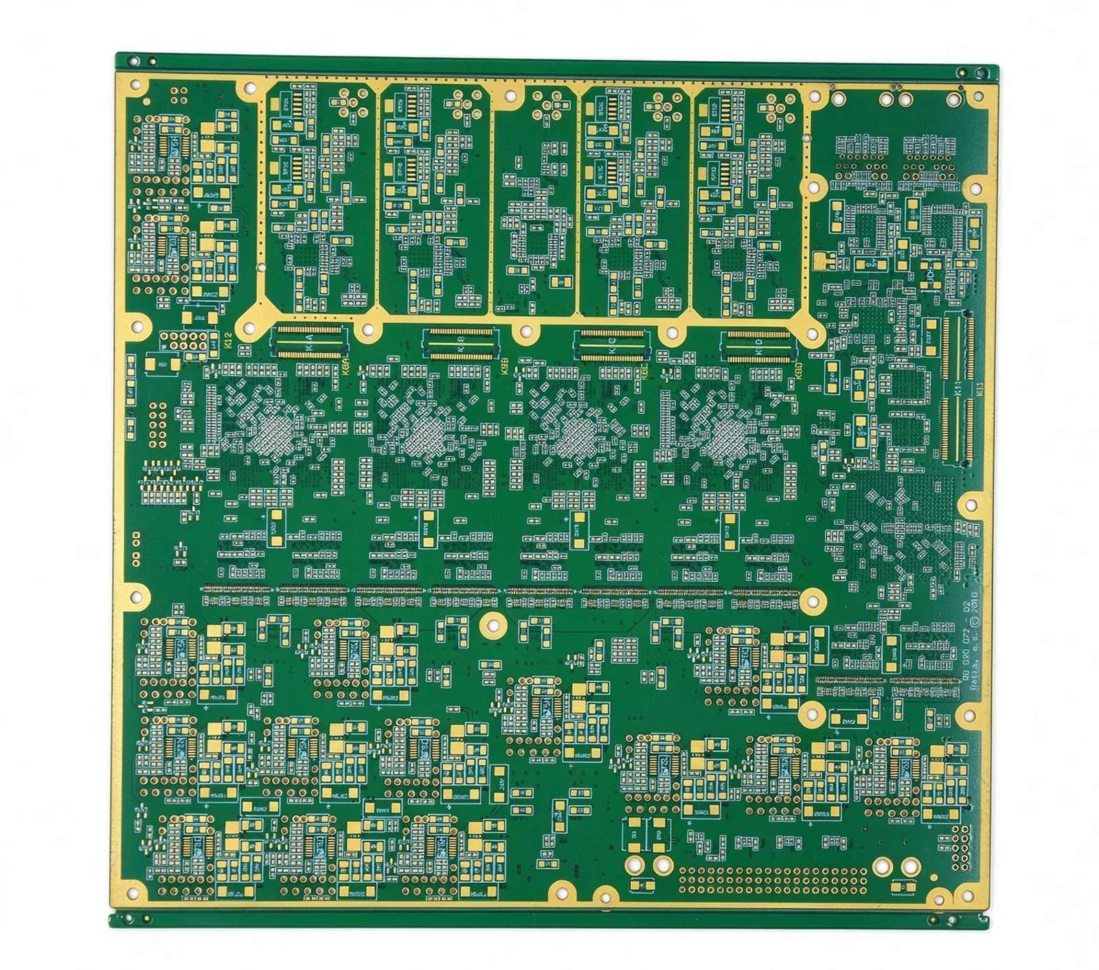
How to Design for HDI: Microvia Stacking and Any-Layer
What each BGA pitch band demands in via type, line width and stack-up, from 1.0 mm down to 0.35 mm.
Read article

A flex tail with a stiffener and a rigid-flex board solve the same mechanical problem from opposite directions. The question is not which is better — it is how many solder joints, connectors and assembly passes the rigid sections remove, and whether that is worth the premium.
The choice is usually framed as flex against rigid-flex, which skips the middle option. A flex circuit with local stiffeners carries components on bonded reinforcement in defined areas; a rigid-flex board has genuine FR-4 sections laminated to the polyimide; and two rigid boards joined by a cable is the baseline everything is compared against.
| Configuration | What it handles | Where it stops working |
|---|---|---|
| Flex with stiffeners | A bend or a fold between two component areas, light parts | Many parts, heavy connectors, repeated assembly handling |
| Rigid-flex | Components on rigid sections, connectors anchored, controlled impedance | Small boards where the flex fraction is high and volume is low |
| Two rigid boards plus cable | Any amount of circuitry, off-the-shelf connectors | Vibration, mating cycles, every extra joint is a field-return candidate |
Stiffeners are bonded reinforcement, not laminate: they add local rigidity for assembly and for part support, but they do not give a flex tail plated through-holes through a rigid stack.
Four things, and all four are mechanical before they are electrical. Component mounting without a stiffener per part; connector anchoring that survives insertion force; controlled impedance held through a laminated rigid stack rather than across a bonded film; and assembly handling that does not depend on how the operator holds a bending tail.
The interconnect count is the number that decides the argument. Removing eighty solder joints from a vibration environment is a reliability decision before it is a cost one, and it is the reason a rigid-flex board survives qualification that a board-cable-board assembly fails — not because any single joint is better, but because there are fewer of them.
A rigid-flex board runs three to eight times a rigid board of the same area. Against two rigid boards plus a connector the premium is smaller — in a typical worked build around 45% — because the comparison baseline moves up. The money goes to five places, and each has a different mechanism.
| Driver | Share of price | Mechanism |
|---|---|---|
| Polyimide and adhesiveless laminate | 20–35% | PI film at 3–5× FR-4, plus adhesive-free bonding at another 1.3–1.5× |
| Coverlay and laser profiling | 10–20% | Every window cut before lamination, held to 0.1 mm |
| Lamination cycles | 10–18% | One to two extra press cycles plus bookbinding |
| Yield loss at flex zones | 10–25% | 5–15% scrap on long tails, compounding across steps |
| Engineering and tooling | 5–15% | Laser program, bend test vehicle, press recipe, fixtures |
Shares are an industry range for medium-volume builds and move with the flex fraction of the board. A design that is 60% flex area sits at the top of the material band, because the premium scales with flex area rather than with total board area.
Two of those drivers surprise people. Coverlay is not a solder mask: every pad opening is cut before lamination, one program feature at a time, at about 0.1 mm accuracy — a tail with sixty exposed pads is sixty cuts against one mask exposure on a rigid board. And yield is a multiplier rather than an adder, because a flex zone is inspected after lamination, again after coverlay and again after test: a defect from the first step survives two more value-adding steps before anyone finds it.
The honest comparison is landed cost per assembled unit, including the connectors, the second assembly pass, the second test fixture and the field-return rate. On that basis the gap narrows to roughly 30 to 50%, and then three things decide it: interconnect count, flex fraction and volume.
Flex fraction is the one that gets missed. On a 160 cm² board with a 40 cm² tail, the material premium applies to a quarter of the board, which is why flex-zone geometry matters more than overall size. A design that is mostly flex has already paid the polyimide price and the rigid sections are then cheap by comparison — the awkward case is the middle one, where a modest flex area carries the full tooling burden.
Volume decides the engineering line. A rigid-flex job needs a laser program, a test vehicle for the bend requirement and a press recipe developed for that bond-ply stack: thousands of dollars before a production panel exists. At 200 units that is a serious share of the price; at 5,000 it is noise. That, more than any technical limit, is why small programs sometimes stay with two boards and a cable.
When the circuit is one or two layers, the components are light and few, and the bend is a fold rather than a repeated motion. A flex tail with stiffeners under the connector and under the LEDs does the job at a fraction of the cost, and it avoids the rigid-to-flex transition that concentrates almost every failure mode in this family.
It also wins when the mechanical envelope is the constraint rather than the circuit. A tail that has to pass through a hinge does not get easier by adding a rigid section to the end of it — and the transition, not the bend area, is where the reliability argument lives.
Four lines settle most of it: the bend radius and whether the bend is static or dynamic, the stiffener material and thickness where stiffeners are used, the impedance requirement through the flex zone if any, and the layer count including polyimide layers. Dynamic bends are a different design from static ones — the copper type and the coverlay both change, and a drawing that does not distinguish them will be quoted for the wrong one.
Our published limit is 16 layers including polyimide, with 50 or more on inquiry. That ceiling is why a rigid-flex decision is worth making early: a design that grows past it after the mechanical envelope is fixed has nowhere to go except back to two boards.
No. A stiffener is bonded reinforcement that adds local rigidity for assembly or part support; a rigid section is laminated FR-4 with plated through-holes and its own layer stack. A stiffener does not let you route through the board, and it does not give you impedance control through a laminated stack.
Because the engineering is front-loaded: a laser program, a bend-test vehicle and a press recipe developed for that specific bond-ply stack all exist before the first production panel. Spread over 200 units that is a large share of the price; spread over 5,000 it is small. It is a volume effect, not a capability limit.
Sixteen including the polyimide layers is our published limit, with 50 or more on inquiry. The practical ceiling is usually set by the number of press cycles rather than by the layer count itself, since each cycle adds its own yield loss and queue time.
Only if it actually moves. A static bend — formed once at installation — and a dynamic bend that flexes in service are different designs: the copper type, the coverlay and the allowable radius all change. A drawing that does not say which one applies will be quoted for the wrong construction.
At the transition, not in the middle of either section. Delamination at the rigid-to-flex boundary after thermal cycling, copper cracking at the bend transition during handling, and coverlay voids after lamination account for most of the loss — which is why the transition gets the review rather than the flex area.
What each BGA pitch band demands in via type, line width and stack-up, from 1.0 mm down to 0.35 mm.
Read article
Two resin systems through one press cycle, a 190 °C compromise profile, and why desmear behaves differently on each plastic.
Read article
Four tolerances, four sensitivities, and why the root-sum-square lands at 7.1% while the worst case reaches 12%.
Read article
Send the mechanical drawing and the bend radius. Quote in 24 hours, with the construction and the stiffener plan named. Every build runs to IPC Class 2 standard, Class 3 on request.