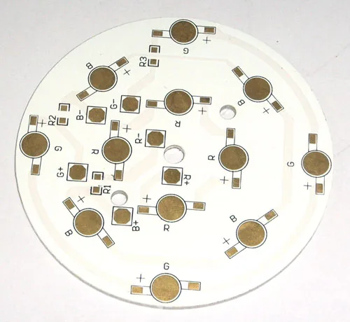
Metal Core LED Layout: Thermal Pad and Isolation Rules
The dielectric sets the thermal limit, not the aluminium: about 0.050 °C/W at 100 µm and 2 W/m·K under a 10 cm² source.
Read article

Aluminum and copper base MCPCBs with thermally conductive dielectric — heat routed by design, edges machined for the enclosure, and a quote back within 24 hours.
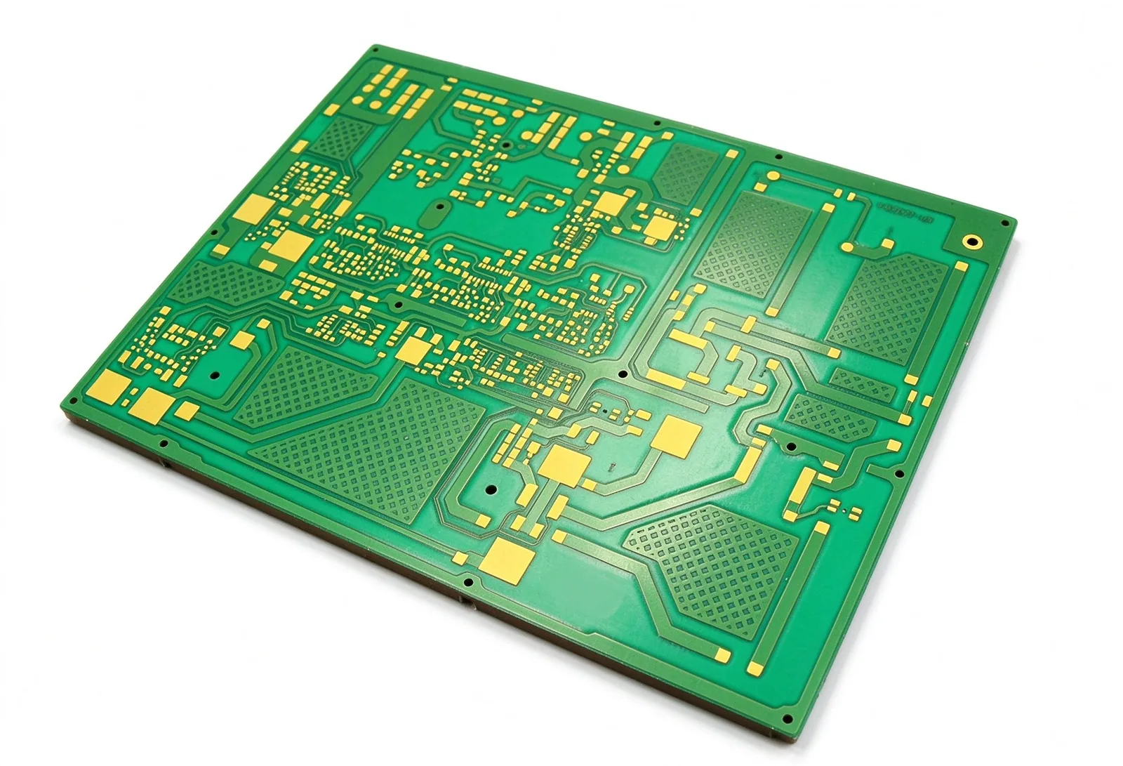
A metal core PCB is built from three things: an aluminum or copper plate as the base, a thin thermally conductive dielectric laid on it, and one or two copper layers on top. The plate carries heat sideways into the housing and stiffens the board mechanically, while the dielectric keeps the circuit isolated from the metal underneath. That construction is why MCPCBs survive LED and power-module loads that would cook an FR-4 board of the same area.
Plenty of shops take an existing FR-4 design, bolt an aluminum plate to the back and call the result thermally enhanced. Nothing in the heat path was designed: dielectric thickness, copper balance and via placement decide junction temperature far more than the base metal does. Expansion mismatch, machined edges and isolation distance also behave differently from FR-4, and those are the failure points that surface after a few hundred cycles.
HSX CIRCUIT starts every metal-core order with a thermal design review — base metal, dielectric grade, copper weight and thermal via pattern checked against your dissipation, working voltage and enclosure before tooling is cut. 80 CAM engineers review 6,000+ designs each month across 8,000 m² of production, shipping to 40+ countries, and each order leaves the floor only after 100% electrical test.
Aluminum spreads heat at lower cost and lower weight; copper moves roughly twice as much and tracks silicon expansion more closely. Dielectric grade runs from 1–3 W/m·K standard to ceramic-filled 8–12 W/m·K for dense junctions — chosen against your load, not by house default.
Heat leaves the die through copper, not through air. Thermal pads and filled or plated vias are sized against the dielectric’s thermal resistance so heat reaches the base plate instead of pooling at the solder joint, with isolation spacing kept intact around each pad.
Metal-backed boards get milled, punched and drilled, not routed like FR-4. Edge quality, slot position and mounting holes are planned around burr, stress and creepage, and dielectric withstand is verified on the finished part to prove the layer still isolates after machining.
The metal plate and the copper above it grow at different rates. Bake, thermal-cycle and flattening steps are set per board so flatness holds after reflow and the dielectric does not craze through repeated field cycles.
| Parameter | Capability |
|---|---|
| Base material | Aluminum 5052 / 6061; copper base (C1100) on inquiry |
| Dielectric layer | 75–150 µm thermal dielectric; ceramic-filled grade for 8–12 W/m·K |
| Thermal conductivity | 1–3 W/m·K standard; ceramic-filled 8–12 W/m·K |
| Board thickness | 0.8–3.2 mm overall (base metal 0.8–2.0 mm) |
| Min trace / space | 0.075 mm / 0.075 mm |
| Layer count | 1–2 copper layers, single- or double-sided; extra layers reviewed on inquiry |
| Thermal vias | Plated or filled through the dielectric to the base plate; pattern set by thermal review |
| Electrical test | 100% — open/short test on every order |
UL 94 V-0 · IPC-6012 / IPC-A-600 · IPC Class 2 standard, Class 3 on request · Full matrix: see Capabilities.
Send your files — a CAM engineer reviews them, not a form.
Dense LED arrays on aluminum base, where heat has to leave the die before colour shift and lumen decay set in.
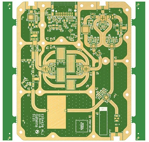
Driver boards where switching loss and copper loss land on the same metal-backed substrate.
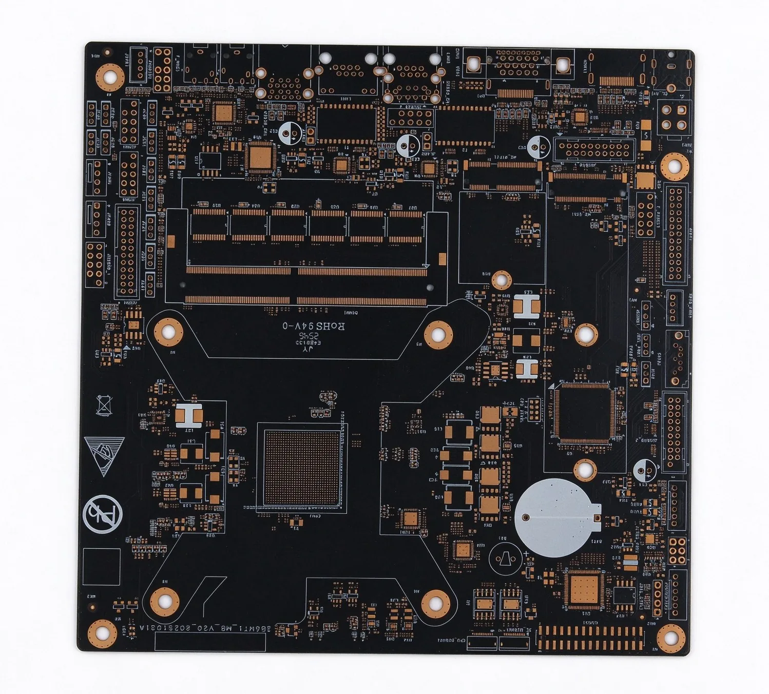
Lamp and module boards that must hold up to vibration, thermal cycling and sealed-housing temperatures.
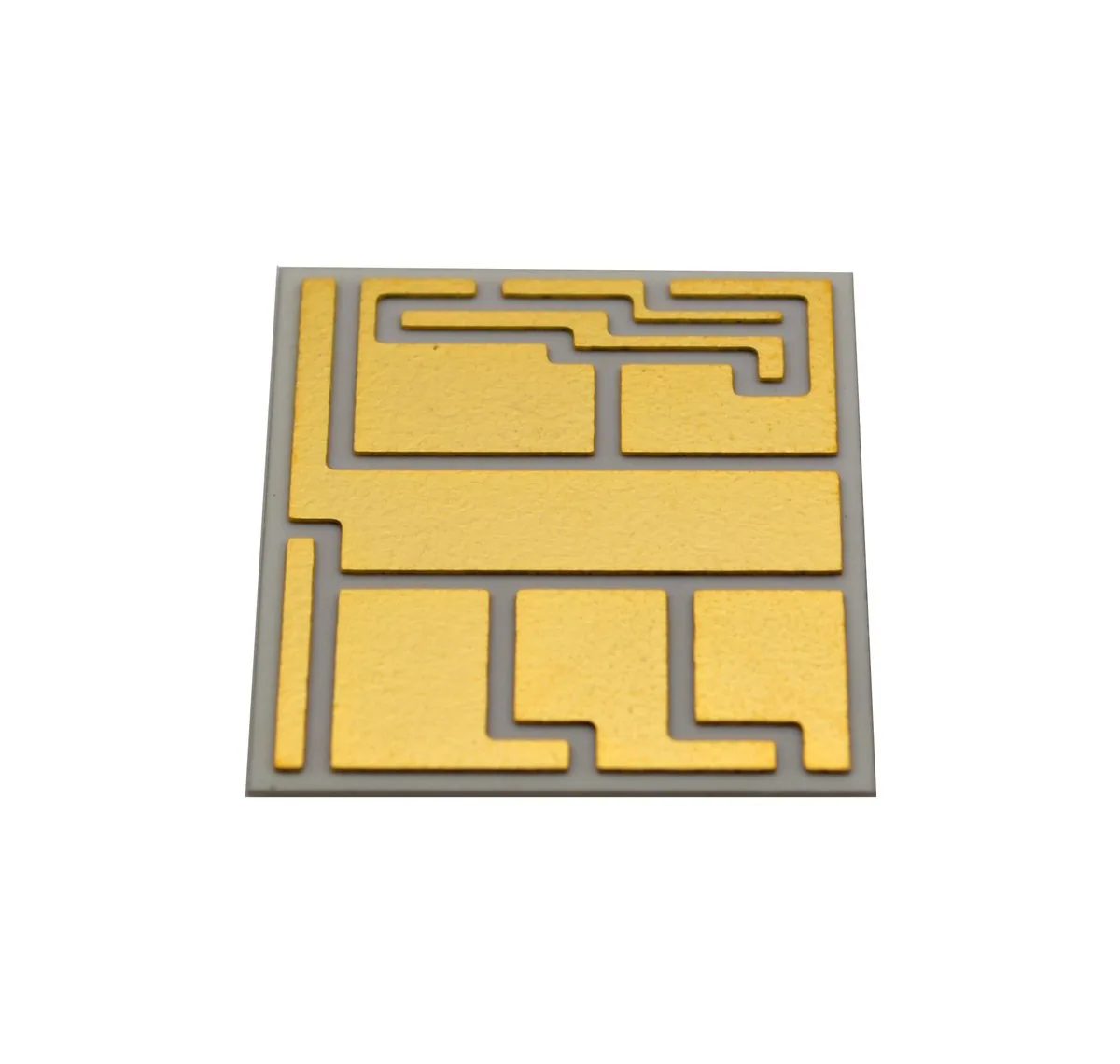
Ceramic-filled dielectric builds for modules with tight isolation distance and high junction density.
The dielectric sets the thermal limit, not the aluminium: about 0.050 °C/W at 100 µm and 2 W/m·K under a 10 cm² source.
Read article
At 3 oz the etchant travels sideways through 105 µm of copper, so the minimum space opens to 0.20 mm and the trace section becomes a trapezoid.
Read article
Alumina at 20–24 W/m·K and AlN at 170 against 0.2–0.3 for FR-4, plus the crossover arithmetic that decides which one ships.
Read article
Aluminum is the default: lighter, cheaper, and it covers most LED and power-supply loads. Copper conducts heat about twice as well and its expansion sits closer to silicon, so it earns the cost on dense power modules and boards that see heavy thermal cycling. The thermal review recommends one per design rather than by default.
The thermal dielectric runs 75–150 µm in production. A thinner layer lowers thermal resistance but trims breakdown margin, so thickness is set by working voltage, creepage requirement and the withstand level you need — then confirmed on the first article.
Single- and double-sided metal-core boards are standard production. A third copper layer or a metal/FR-4 hybrid stack is reviewed case by case; send the proposed stack-up and we confirm feasibility at quotation.
Gerber (RS-274X) or ODB++ with drill data, plus the base metal, dielectric grade and copper weight you intend to use. A thermal drawing or a junction-temperature target helps us quote the dielectric correctly. Upload through the quote page — a CAM engineer, not a form, reviews the files.
Lead time depends on base metal, dielectric grade and machining, and is confirmed at quotation. Rush options are quoted with the order, and anything that puts the schedule at risk is raised before the panel is released.
Metal-backed construction only pays off when the stack is engineered for it. Quote in 24 hours.