Rigid-Flex vs Flex: When the Extra Rigid Layers Pay Off
Three configurations, five cost drivers, and the interconnect count that decides whether the rigid premium comes back.
Read article

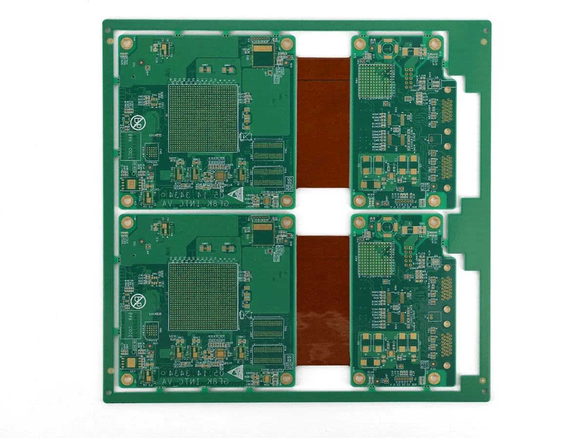
Polyimide flex zones bonded into rigid sections during one lamination — so the board bends where the enclosure needs it and stays stiff where the components sit.
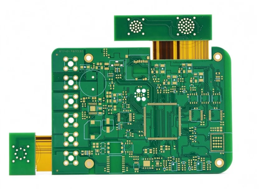
A rigid-flex PCB laminates polyimide flex layers into rigid FR-4 sections in the same press cycle. The board bends where the product folds and stays flat where the components sit, and the interconnect that used to be a cable plus two connectors becomes copper inside the board.
That trade is worth making whenever a product pays for every connector it carries: each removal deletes a solder joint, a mating tolerance and a failure point. Rigid-flex recovers volume in handheld and wearable devices, absorbs motion in folding and camera modules, and holds impedance through the bend instead of handing the signal to a ribbon cable.
Some suppliers bolt a flex line onto a rigid shop and buy the flexible portion as a part. We build the whole board as one system instead — rigid stack-up, bend area, stiffener and connector footprint reviewed together, because failures concentrate at the transition rather than in the middle of either section. That review runs through the same pool of 80 CAM engineers that handles 6,000+ designs a month, so a bend-radius or stiffener conflict is raised before tooling, not after the first panels fold wrong.
Flex cores and rigid prepreg move differently through the press, so registration is planned outward from the artwork and checked at every bond layer. Vacuum-assisted lamination with a slow cure profile keeps air out of the bond line — a trapped void at a rigid-to-flex boundary turns into an open after thermal cycling.
Coverlay decides where copper may be exposed and where it must stay sealed. Openings are cut and registered to the pad geometry, so a connector tail does not collect adhesive bleed across its contacts and bend areas keep uninterrupted insulation.
In a bend zone, conductors run widely spaced and cross the bend perpendicular, with no via or plated hole inside the flex. FR-4, aluminium or polyimide stiffeners are then bonded where the connector or component needs support, placed outward from the bend line.
Most cracks begin where rigid meets flexible. Fillets and a staggered rigid-to-flex boundary spread the strain, drill and routed edges are held away from the transition, and the design is checked against the real bend direction before release.
| Parameter | Capability |
|---|---|
| Layer count | Up to 16 layers including polyimide flex layers |
| Flex core thickness | 0.2 mm flexible construction on inquiry |
| Min trace / space | 0.075 mm / 0.075 mm |
| Layer-to-layer registration | ±50 µm |
| Rigid section thickness | 0.4–6.0 mm |
| Stiffener materials | FR-4, aluminium, polyimide — bonded and registered to the bend line |
| Impedance control | ±5% standard, ±3% on request; coupon measured on every lot |
| Electrical test | 100% on every board — flying probe for prototypes, fixture for volume |
UL 94 V-0 · IPC-6012 / IPC-A-600 · IPC Class 2 standard, Class 3 on request · Full matrix: see Capabilities.
Share the outline and bend line — we review coverlay and stiffener clearances with you.
Handheld analysers where one rigid-flex replaces three cable assemblies.
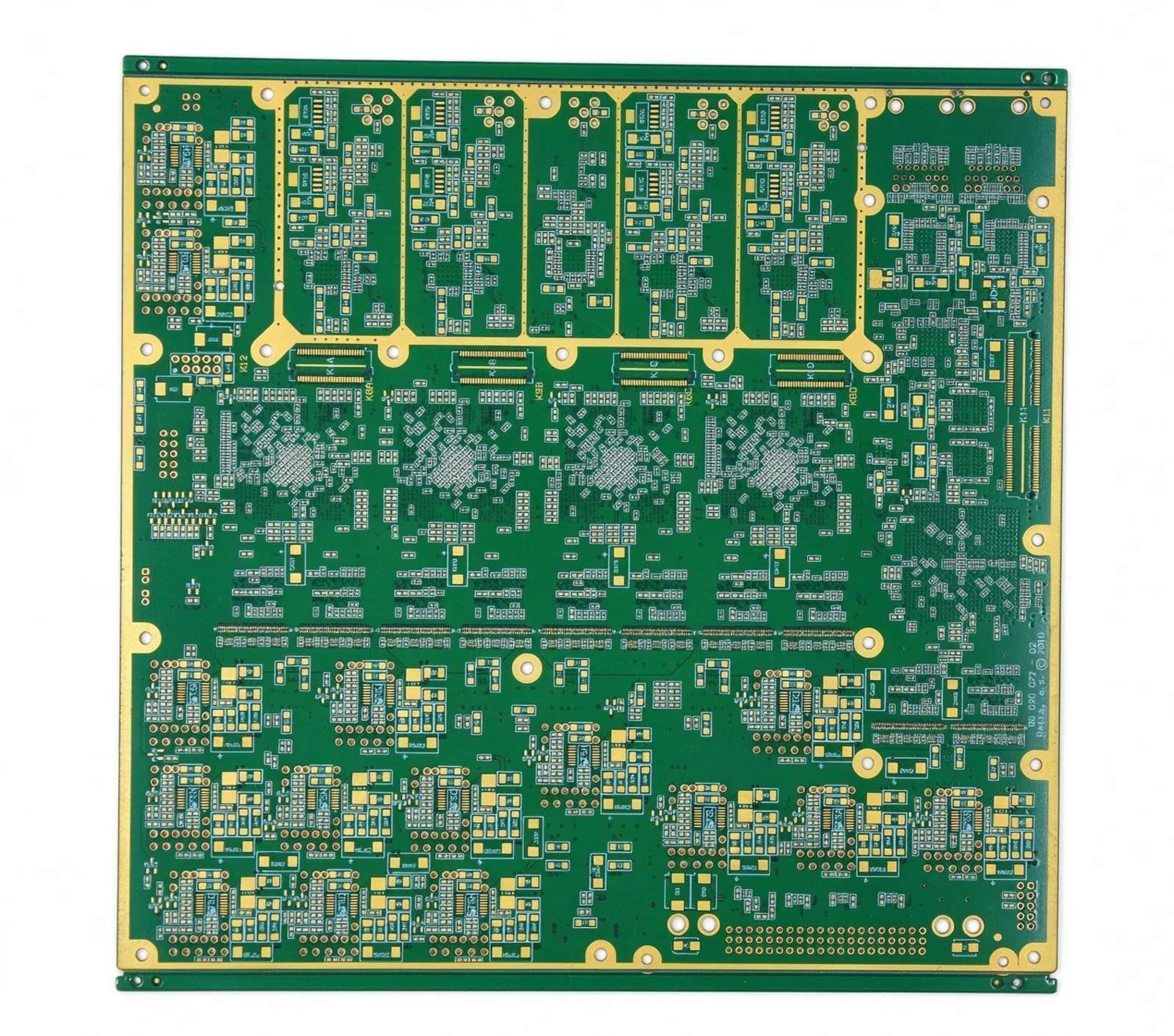
Skin-contact sensor patches that move with the body and stay electrically quiet.
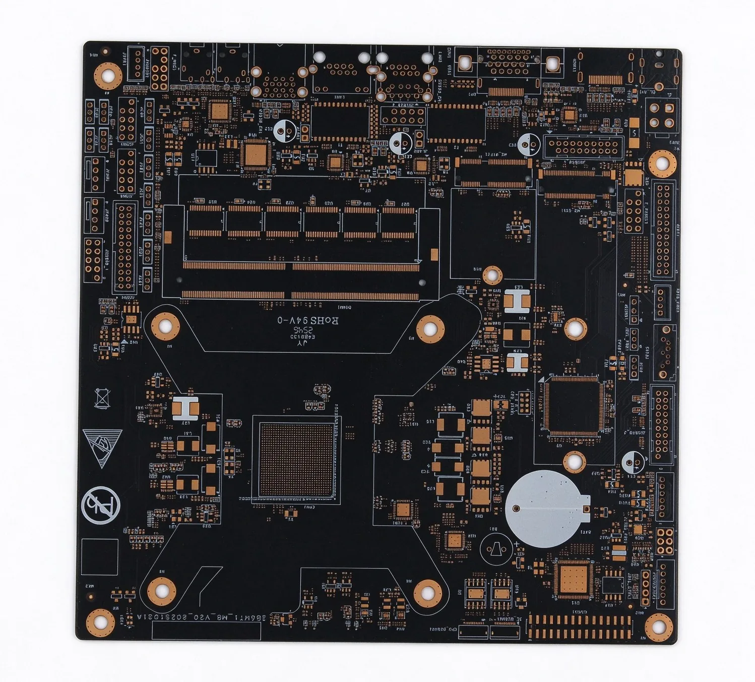
Hinge-crossing sensor boards with the bend zone designed for a defined cycle count.
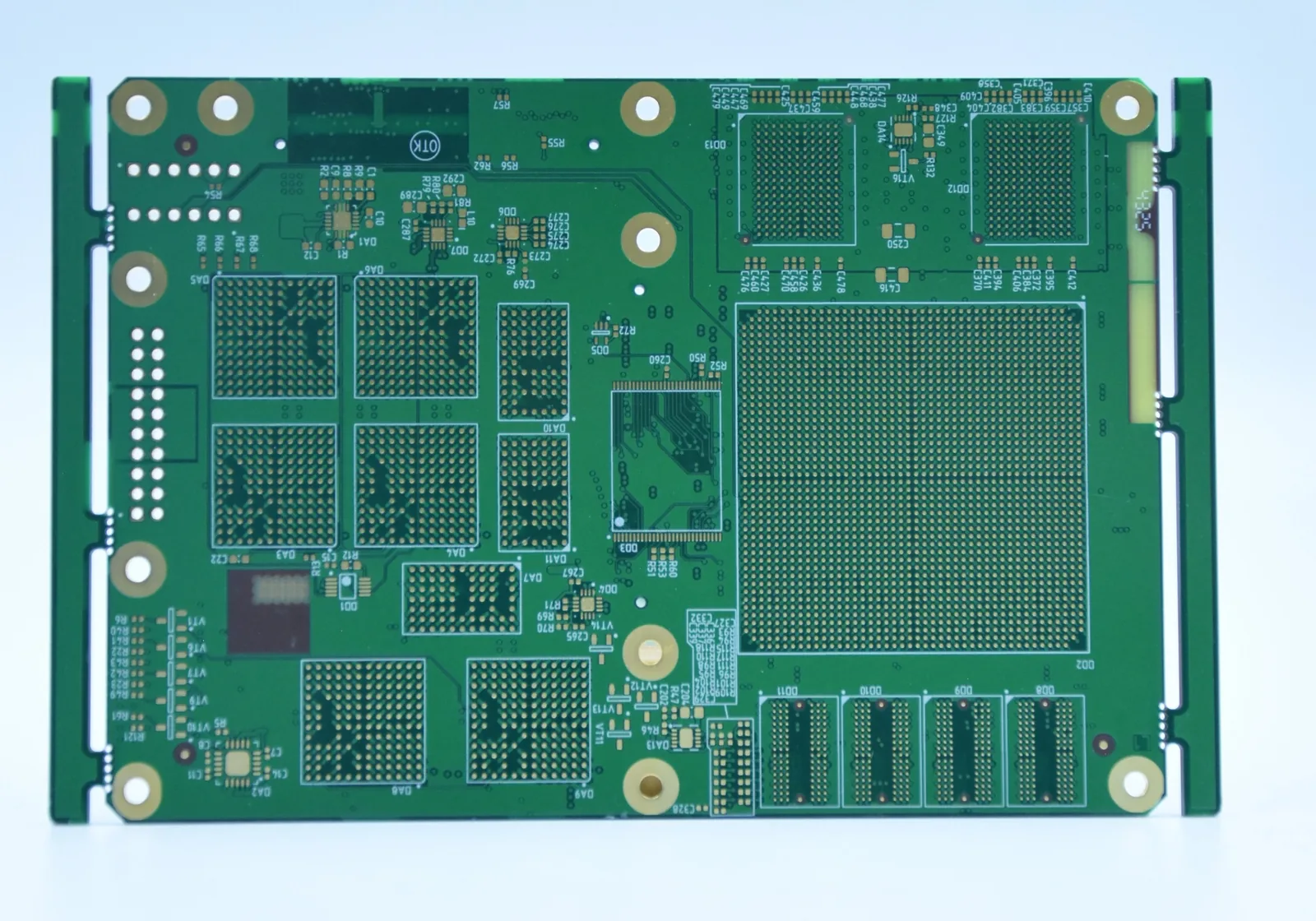
Camera and radar modules whose flex tails survive vibration and temperature swing.
Three configurations, five cost drivers, and the interconnect count that decides whether the rigid premium comes back.
Read article
What each BGA pitch band demands in via type, line width and stack-up, from 1.0 mm down to 0.35 mm.
Read article
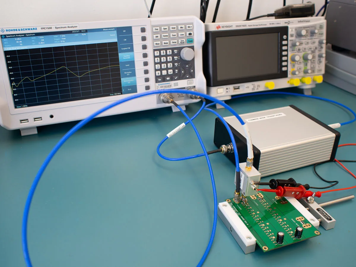
Four tolerances, four sensitivities, and why the root-sum-square lands at 7.1% while the worst case reaches 12%.
Read article
On the finished construction, not from a laminate datasheet: coupons from the same panel are cycled to your radius and stroke count, and the copper type — rolled annealed or electrodeposited — is chosen from the result. A dynamic cycle target beyond standard testing is quoted as a dedicated validation lot.
Rigid sections follow the normal 0.4–6.0 mm range; the flexible portion targets a balance between bend radius and stiffness, with 0.2 mm flex constructions available on inquiry. Both are fixed together at engineering review because they share one lamination.
Yes — FR-4, aluminium or polyimide stiffeners are bonded and registered to the connector footprint or component area. Give us the connector part number and mating force, and the stiffener is placed so the tail does not peel.
Gerber or ODB++ with the rigid and flex outlines, the bend line, layer construction and stiffener intent, plus a STEP model if the board folds into a housing. An unclear bend line is the most common reason a rigid-flex quote needs a second round.
Lead time is confirmed at quotation once the construction and validation requirements are settled. Schedules that include bend cycling or a first-article report carry that time in the quote instead of revealing it later.
Bring us the bend line and the enclosure. Quote in 24 hours.