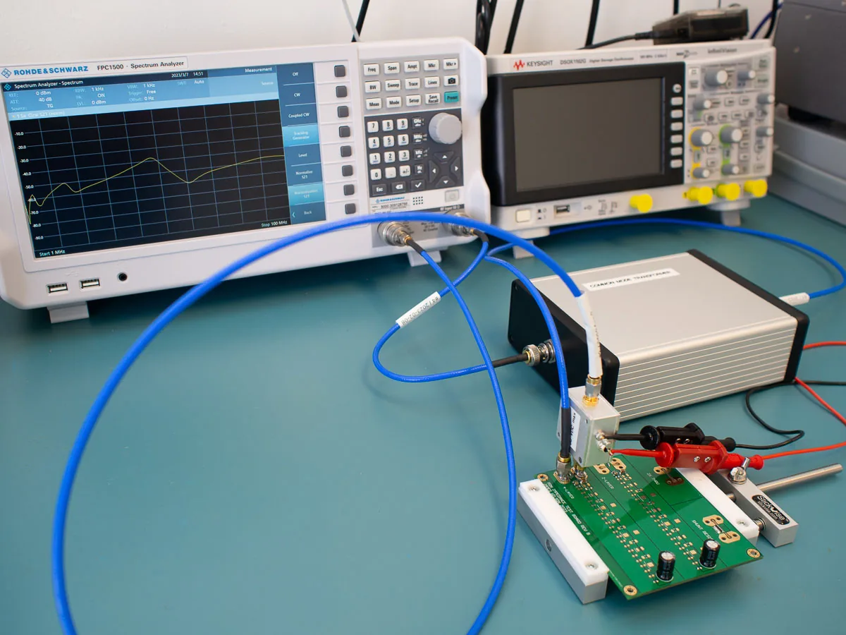
Controlled Impedance Tolerances: ±5% versus ±10%
Four tolerances, four sensitivities, and why the root-sum-square lands at 7.1% while the worst case reaches 12%.
Read article

A hybrid board exists because one material cannot do both jobs: the RF section needs a stable Dk at 10 GHz and the digital section needs cheap, well-understood FR-4. The difficulty is not in either material — it is in the interface between them.
A typical hybrid puts the RF laminate on the outer layers, or as a symmetric pair around the centre, with FR-4 carrying the digital routing. The bonding layer between them is thin — often 0.1 mm or less — and it has to accommodate the CTE difference between two plastics while bonding to copper on both sides. Every failure mode in a hybrid board starts at one of those interfaces.
Symmetry matters more here than in an all-FR-4 stack. Two different materials on opposite sides produce asymmetric expansion, and the board bows as it cools from cure. That bow shows up as a warpage failure at final inspection and as a coplanarity problem at assembly. The design defence is material symmetry: equal RF laminate thickness on both sides, or one RF side balanced by an FR-4 thickness chosen to match its expansion contribution.
Dk and Df only compare at a stated frequency and method. 4350B is specified at Dk 3.66 and Df 0.0037 at 10 GHz; an FR-4 datasheet quoting Df at 1 GHz does not sit beside those numbers, because loss rises with frequency. Any laminate comparison in a stack-up review that omits the frequency is comparing two different measurements.
| Parameter | 4350B | High-Tg FR-4 | Condition |
|---|---|---|---|
| Dk | 3.66 | 4.2–4.6 | At 10 GHz for the RF laminate, 1 GHz for FR-4 |
| Df | 0.0037 | 0.015–0.020 | At the stated frequency |
| Tg | Above 280 °C | 170–180 °C | DSC |
| Z-axis CTE | ≈32 ppm/°C | 45–55 ppm/°C | Below Tg |
| Td | Above 400 °C | 300–340 °C | TGA |
RF laminate values follow the supplier datasheet and are quoted with their test frequency. FR-4 values are a typical window that varies by grade and is governed by the slash sheet rather than by a plant default. Td uses the TGA method, not the DSC method used for Tg.
The RF laminate’s Tg sits well above the FR-4 cure window, so the press does not soften it. Its Z-axis CTE of about 32 ppm/°C against 45 to 55 for high-Tg FR-4 sets the interface strain: with a 55 ppm/°C laminate and a 100 K swing the difference is 0.23%, acting on a bond line around 100 µm thick. That is why the bonding film’s elongation matters as much as its Dk.
There are three routes, and the choice is set by what crosses the interface rather than by price. A bondply from the RF laminate family keeps Dk continuous across the interface and flows close to the RF laminate’s own window. A low-flow FR-4 prepreg controls resin movement so the RF laminate does not end up under a resin-rich layer. Standard FR-4 prepreg is the cheap route and accepts a Dk step at the interface.
| Bonding option | Where it fits | Main concern |
|---|---|---|
| RF-family bondply | An RF trace crosses the interface | Dk continuity; higher material cost |
| Low-flow FR-4 prepreg | Standard hybrid, no RF crossing | Resin flow control, 0.1 mm bond line |
| Standard FR-4 prepreg | Cost-first, digital routing only | Dk step at the interface |
State on the drawing which case applies. Without that note the fabricator chooses by cost, and the choice is invisible until an impedance measurement crosses the boundary.
The distinction is easy to test: does an RF trace run from the laminate into the FR-4 section? If not, the interface only has to survive thermal cycling and the cheap route is defensible. If it does, the Dk step reflects at the transition and the matched bondply is the only route that keeps it small.
The profile has to cure the FR-4 prepreg and flow the bonding layer without over-curing either. In practice the hold lands near 190 °C, inside the FR-4 cure window and close to the bonding film’s recommended range, with a ramp slow enough that both materials reach temperature together.
| Stage | Setting | Why it matters here |
|---|---|---|
| Ramp | 1.5–3 °C/min | Lets both plastics reach temperature together |
| Hold temperature | 185–195 °C | FR-4 cure window and bonding film flow range |
| Hold time | 60–90 min | Cure completion without over-flow |
| Pressure | 1.4–2.8 MPa, adjusted down for thin bond lines | Controls bond-line thickness |
| Cool-down | Controlled, under pressure | Prevents bow from asymmetric expansion |
Typical windows for a hybrid FR-4 and hydrocarbon laminate build. The exact profile follows the bonding material datasheet, and the hold time is set by the thickest FR-4 section in the stack rather than by the panel size.
Both edges of that window fail, and they fail differently. Too cool and the bonding layer does not flow: the interface keeps micro-voids that a C-SAM scan finds and a thermal cycle opens. Too hot and the FR-4 resin flows out of the bond line, thinning and starving the interface while the RF laminate sees a cure beyond its datasheet. Both look similar at final inspection and both are diagnosed from bond-line thickness in a cross-section.
The RF laminate is filled and ceramic-loaded, so it abrades drill bits faster and behaves differently from FR-4: lower spindle speed and higher feed are the usual starting point, with bit life shortened to protect hole quality. A panel that drills FR-4 at one recipe and the RF laminate at another needs either a recipe change mid-panel or a tool list that separates the two zones. Entry and exit material matter more here, because the filled laminate chips at breakout.
Desmear is the part that catches people out. Permanganate is tuned to FR-4 resin chemistry and the hydrocarbon laminate etches less per cycle, so a recipe carried over from an all-FR-4 build can leave smear in the RF zone. Plasma desmear treats both surfaces without that chemistry dependence and is the usual route where the hybrid carries microvias.
Whichever route is used, the check is the same: a section through one via in each zone, not one via total. A single cross-section taken from the FR-4 half proves nothing about the RF half, and the RF half is where the smear hides.
Start with bond-line thickness in a cross-section at the interface, because it carries the evidence for both over-flow and starvation. Then measure warpage on the finished board against the 0.75% limit in IPC-6012. Then run a thermal cycle with a C-SAM read before and after, which finds interface voids the first scan missed because they were below the resolution limit.
The standards divide along material lines: the FR-4 half is specified under IPC-4101 with peel strength assessed in bands, and the RF half through the IPC-4103 slash sheets where the Dk tolerance and the loss figure come from. Board-level acceptance including warpage comes from IPC-6012. A hybrid drawing should cite all three, each against the half it governs — and keep the acceptance criteria separate from the press recipe, because the standards define a good board rather than how to make one.
Yes, when no RF trace crosses the interface. Standard prepreg flows more than a low-flow grade, so the bond line can thin under pressure, and its Dk differs from the RF laminate, which creates an impedance step. Where an RF trace transitions between the two, use a matched bondply and state the requirement on the drawing.
Because the two materials expand differently and any asymmetry in their placement turns that difference into bow. A stack with RF laminate on one side only needs an FR-4 thickness chosen to balance it. Warpage is checked on the finished board against the 0.75% limit, not at the press — by then the asymmetry is already built in.
Usually yes. Permanganate is tuned to FR-4 resin chemistry and the hydrocarbon laminate etches less per cycle, so a recipe carried over from an all-FR-4 build can leave smear in the RF zone. Plasma desmear avoids the chemistry dependence and is the common choice where the hybrid carries microvias.
FR-4 falls under IPC-4101, including peel strength bands and the Tg test method. High-frequency laminates are specified through the slash sheets of IPC-4103. Board-level acceptance, warpage included, comes from IPC-6012. A hybrid drawing should cite all three.
When the RF section is small relative to the board and the digital routing does not need low loss. The saving comes from replacing RF laminate area with FR-4, so it scales with the ratio of the two areas — and it disappears if the RF traces have to cross the interface and force a matched bondply across the whole panel.
Four tolerances, four sensitivities, and why the root-sum-square lands at 7.1% while the worst case reaches 12%.
Read article
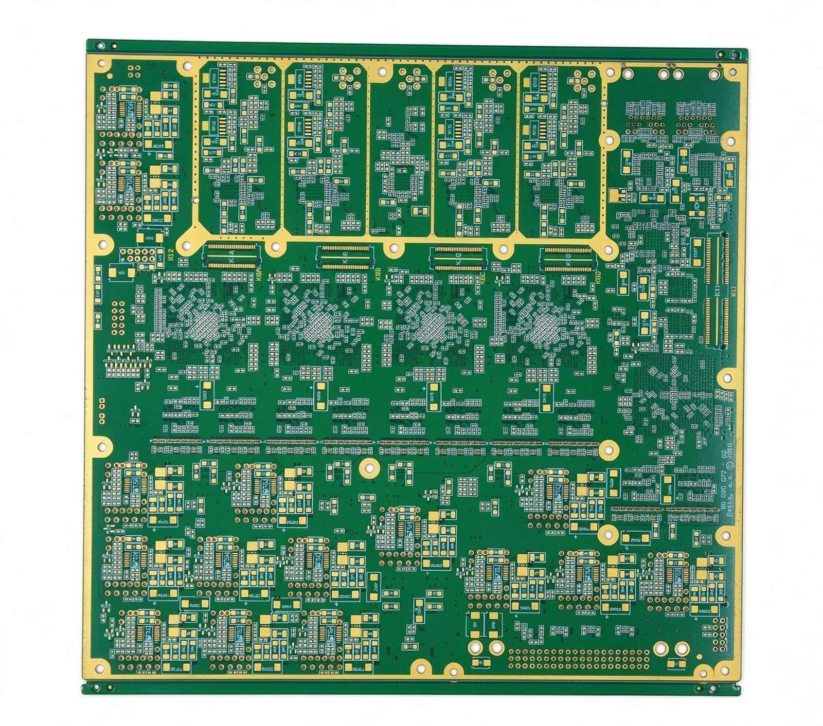
What each BGA pitch band demands in via type, line width and stack-up, from 1.0 mm down to 0.35 mm.
Read article
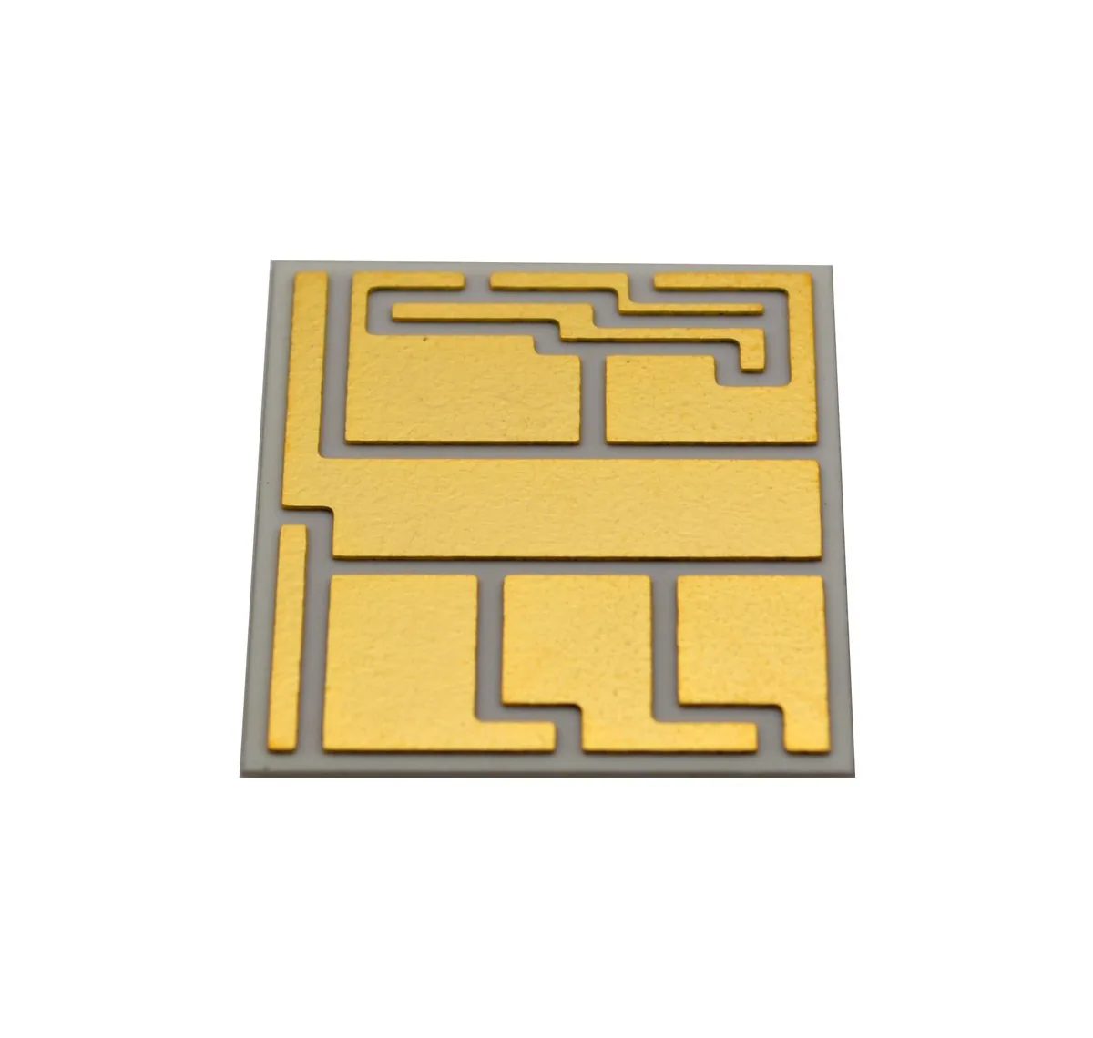
Alumina at 20–24 W/m·K and AlN at 170 against 0.2–0.3 for FR-4, plus the crossover arithmetic that decides which one ships.
Read article
Send the stack-up and the frequency plan. Quote in 24 hours, with the bonding route and press profile named. Every build runs to IPC Class 2 standard, Class 3 on request.